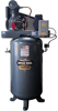
![]() January 17, 2012: Through this partnership, Tsunami will offer to the marketplace a complete compressor and dryer package built into one integrated system. Saylor-Beall a manufacturer of industrial grade air compressors for more than 90 years, built its reputation on quality and the proven ability to meet the special needs of their customers. They are known for industrial quality designs, prompt shipments and custom applications. Through an on-going program for continuous improvement, Saylor-Beall has developed better materials, designs and manufacturing processes. This has resulted in an outstanding line of quality air compressors that meets the needs of the most rugged applications. Tsunami Compressed Air Solutions is a complete line of products designed and developed to assist customers in obtaining dry, clean air for their specific application needs. The systems use the latest technology to provide the cleanest, driest compressed air available. Use of the Tsunami products can help save 10%-15% of compressed air energy costs. Check out Clark Heintz Tools & Equipment's line of awesome Saylor Beall air compressors here.
January 17, 2012: Through this partnership, Tsunami will offer to the marketplace a complete compressor and dryer package built into one integrated system. Saylor-Beall a manufacturer of industrial grade air compressors for more than 90 years, built its reputation on quality and the proven ability to meet the special needs of their customers. They are known for industrial quality designs, prompt shipments and custom applications. Through an on-going program for continuous improvement, Saylor-Beall has developed better materials, designs and manufacturing processes. This has resulted in an outstanding line of quality air compressors that meets the needs of the most rugged applications. Tsunami Compressed Air Solutions is a complete line of products designed and developed to assist customers in obtaining dry, clean air for their specific application needs. The systems use the latest technology to provide the cleanest, driest compressed air available. Use of the Tsunami products can help save 10%-15% of compressed air energy costs. Check out Clark Heintz Tools & Equipment's line of awesome Saylor Beall air compressors here.
HEINTZ EQUIPMENT, LLC
1298 RTE 3A BOW, NH 03304
- Register
- Log in
- Wishlist (0)
- My Cart (0) You have no items in your shopping cart.
HEINTZ EQUIPMENT, LLC
1298 RTE 3A BOW, NH 03304
- 2026
- 2025
- 2024
- 2023
- 2022
- 2021
- 2020
- 2019
- 2018
- 2017
- 2016
- 2015
- 2014
- 2013
- 2012
- 2011
- 2010
2012, January
Not all air compressors are created equal. Aside from tank size, horsepower, and PSI ratings, of course, they pretty much look and operate the same way. What many users may not realize however, is that there are more important differences than meet the eye, particularly when it comes to the compressor pumps themselves. The first mechanical compressors were used hundreds of years ago by blacksmiths. Used for generations, these simple bellows-type compressors became museum pieces during the Industrial Revolution with the introduction of piston power. Originally used in steam engines to drive machines, pistons were soon adapted to a wide range of other uses, including air compression and storage for future use. Today's compressor pumps are based on the same principles.
However, they have evolved significantly over the years, and have become the heart of many durable, high performance machines. Understanding the differences among these components can help users determine which air compressor is right for their needs.
The basics of piston-type pump operation Most air compressors are reciprocating or piston-type air compressors. Their operation is similar to an automotive engine. Inside the pump, a crankshaft moves a set of pistons up and down. On the down-stroke, air is drawn into the compression chamber through a one-way valve; as the rising piston on the up-stroke compresses the air, a second one-way valve opens to force the air into a pressure tank. As more air is forced into the tank, the pressure inside the tank rises. Most pumps are either single-stage or two-stage. The difference refers to the number of times intake air is compressed in a pump. A single stage compressor compresses intake air one time before sending the air into a storage tank. Single-stage air compressors can have one, two, or four cylinders, but the air is only compressed once. Most single-stage air compressors have a maximum pressure of 125 PSI. Two-stage air compressors compress air twice before sending it into a storage tank. A two-stage compressor has a minimum of two cylinders: a low-pressure cylinder (largest) and a high-pressure cylinder (smallest). Air is compressed once in the large cylinder and then sent through an air cooling tube, which reduces discharge air temperatures. Lower temperatures improve operating durability and efficiency. In most lower horsepower compressors, the interstage coolers use the same airflow that cools the rest of the compressor pump structure. In larger compressors, as well as in some special applications, water cooled interstage coolers may be used. Upon reaching the small cylinder, the air is compressed again. Two-stage air compressors produce a larger volume of air at higher pressures than smaller single-stage compressors. Two stage air compressors have a maximum pressure of 175 PSI.
Pump cylinders A wide variety of cylinder arrangements and designs are used in compressor pumps. These include a single vertical cylinder, dual vertical in-line cylinders, dual horizontal opposed cylinders, and single "V" or "W" designs made by combining two sets of in-line cylinders. The number and size of cylinders used is dependent on the capacity required and the number of stages. Multiple cylinders may be used in single stage compressors. Usually all the cylinders will be the same size. In two-stage compressors, the size of each successive stage cylinder is reduced as the air passed from cylinder to cylinder requires less space at each stage. Cylinders are made from machined castings that can be solid cast iron, die cast aluminum (with or without an iron or steel bore liner), or from solid aluminum. Solid cast iron is considered the most durable. For small oilless compressors, cylinders formed from aluminum tubing are often used. The cylinders may be separate from the crankcase and cylinder heads, or may be cast together with the crankcase or the cylinder head. For easier serviceability, having the crankcase separate from the cylinder is preferred. External fins on the cylinder combined with cooling airflow dissipate the heat of compression in air-cooled types.
Oilless, splash, and pressure lubrication Air compressors and their pumps are no different from other large machines in that proper lubrication is essential to insure long life and maximum service from an air compressor. Three types of lubrication systems are used in compressors: oilless, splash and pressure. In oil-free and oilless compressors, there is no oil on the cylinder walls. Oilless designs depend on the self-lubricating materials to allow the piston to slide in the cylinder and the grease in the sealed bearings. Splash lubrication relies on an oil dipper attached to the bottom of the connecting rod, which randomly splashes oil from the crankcase reservoir onto the bearings and internal parts of the compressor to keep them properly lubricated. This is the most common form of lubrication and is used in most reciprocating type air compressors. Pressure lubrication uses an oil pump driven by the crankshaft to draw oil out of the crankcase. It is then filtered and pumped through passageways in the crankshaft to the connecting rod bearing surfaces. This action provides direct, positive lubrication to these critical parts. Oil also sprays onto the cylinder walls lubricating the piston and piston bearings. A pressure lubrication system costs a little more, but delivers superior lubrication and is the system of choice for heavy-duty industrial service.
Drives Electric motors and internal combustion engines are most commonly used to drive the air compressor pumps. Direct drive and belt drive arrangements are available. Small single stage oilless compressors for home and light commercial use are generally direct drive electric motor designs. Small oil lubricated machines may be direct drive electric or belt drive. Larger oil-lubricated machines from 5 to 25 HP are almost exclusively belt drive. Only a few small oil lubricated units are built direct drive with internal combustion engines. Some special configurations use power takeoff drives in service trucks and heavy equipment. Drive design must take into account the torque fluctuation of both the compressor and the driver. Flywheels are selected to give the optimum combination of inertia to minimize fluctuations but still allow start-up under adverse conditions. In direct drive designs, the motor may be integrated with the compressor, sharing a common shaft and support structure as in small oilless types or may be connected with a coupling for larger sizes. In all cases the drive components must be properly shielded for safety and comply with OSHA requirements. Compressors for use in the home usually meet even more stringent UL requirements. Belt drive designs may use vee, poly vee, or multiple belts, and may require periodic maintenance. Most direct drive designs require little or no maintenance.
Selecting an Air Compressor The relation of compressor pumps to performance is critical when making your compressor purchase decision. Although the number of air compressor choices can be overwhelming, selecting the right mode; can be made easy by asking a few important questions. For what applications will the air compressor be used? Air compressors are used for jobs ranging from inflating tires to operating a factory. The application will determine the type of air compressor needed. Portable single-stage air compressors are used for one person operating air tools. Contractor air compressors are recommended when minimal weight, portability, and low maintenance is important. Stationary, single-stage air compressors are used for small shops in a garage or maintenance facility. Two-stage air compressors are recommended for industrial applications. What tools will be used, and how much CFM is needed? Some tools require more air (CFM) than others do. For example, sanders require more air than an air drill or air ratchets. Also the number of tools operated at once is a factor. How often will the air compressor be used? For regular use (several times per week), select an air compressor with 50/50 duty cycle such as a portable, contractor air compressor. For commercial/Industrial use (daily), select a higher duty cycle air compressor such as high performance, single-stage or two-stage air compressor. Do you have plans for future expansion? If you expect to need more air for more uses in the near future, it is less expensive to buy up to the next larger air compressor than to purchase a second compressor in the future. What type of power is available? Portable air compressors typically operate on 115 volt, 15 amp circuits. Stationary, single-stage compressors and some large portable compressors operate on 230 volt, single-phase power. Two-stage air compressors 10 HP and larger operate on three phase power only, 5 and 7.5 HP. Two-stage compressors are available for single-phase and three-phase power. If no electrical power is available, gas engine air compressors are required.
Now you know Although a first glance at a piece of equipment like an air compressor can be intimidating, a bit a knowledge and insight will make this easier. It's really no different than shopping for a car. By doing your homework, shopping around, and asking the right questions, you will find the best air compressor to fit your needs.
Check out Saylor Beall Compressors and FS Curtis Compressors here.
I mentioned in a previous blog a little bit about our quest to reach customers all over the country with our online shopping cart. We have been so fortunate to have worked with so many of you who reside both near and far... We have been optimizing our website for the last year and I thought it might behoove our potential customers who might be on the fence about ordering equipment from several states away, to see our analytics with regard to our online sales and customer following. So I opened up our online sales administration page and made a list of all the states that were represented-- 36 states in total. I can't say this number represents ALL of our sales, as we do have a large number of folks who call us after finding us on the web, so they are 'unaccounted for' in this particular analysis. Here is the list of the states from where our 2011 online customers hail: Illinois New Jersey Maine Connecticut Michigan Alabama California North Carolina Oregon Arizona Louisiana Maryland Massachusetts Kansas Iowa New York Nebraska Rhode Island New Hampshire Texas Utah Minnesota Ohio Washington Colorado Pennsylvania Vermont Montana Indiana Florida Nevada Virginia Tennessee Wisconsin Georgia Mississippi I found it interesting that of those states, the highest volume of sales were from California, Texas and New York!
UPDATE! After conferring with Clark, I have verified that we have, in fact, sold to all contintental US 48 states! Direct phone calls have closed the gap! We are thankful that folks from all corners of the country have found us to be transparent in our mission and reputation to give us a chance to do business with. We continue to grow an ample presence online with the hope of gaining even more followers. Thanks for all your support. We couldn't do this without our customers!

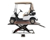
Below you will find the Handy Motorcycle Lift SAM 1000 Instructions and Parts diagrams and lists. We find its been helpful for folks perusing our blog to post documents provided by some of our manufacturer partners. We post all of these PDFs on our website as they become available to us (you will find this particular pdf in the product description for the Handy SAM 1000), but since they are setup as a clickable link, sometimes they can get overlooked. We are grateful for your feedback as it steers us in the right direction - please keep it coming! We are always interested in learning more about what you'd like to see on this blog! Best wishes for a Happy New Year, Clark Heintz Tools & Equipment LLC HANDY S.A.M 1000 AIR LIFT
PARTS LIST AND INSTRUCTION  1. Center load on table - 1000 lb. maximum.
2. Connect to 100 psi maximum shop air.
3. Keep safety bar in position at all times - except when lowering.
4. Keep hands and tools from under carriage. 5. Do not mount table when in elevated position.
6. Do not ride vehicle onto lift.
7. Lift must be in the lowered position when moving.
8. Only trained persons should operate Air Lift.
9. The working area should be sufficiently lit.
10. Foot controller should be at least 3 feet away from Air Lift during raising and lowering operation.
11. Lift is recommended for indoor use only.
INSTRUCTIONS UNPACKING AND SET-UP
1. Open carton, then remove ramp and shipping boards.
2. CAREFULLY TURN TABLE UPRIGHT INTO OPERATING POSITION BEFORE REMOVING SHIPPING CABLE RESTRAINT FROM SCISSOR MECHANISM.
3. Connect foot-operated air valve to 100 psi maximum air supply. The lift may be damaged and/or personal injury may result if the pressure exceeds the maximum 100 psi rating.
4. Stand clear of lift table, and depress the UP side of foot valve to raise table.
5. To lower table, lift detent bar from safety latch and lower to next position or to floor.
6. Place drop-out cover over dropout opening.
7. Insert ramp mounting pins into holes at either end of table to mount ramp.
NOTE: If cycle vise is being installed, ramp must be mounted opposite the cycle vise. OPERATION
1. Loads must be centered on table at all times. Table is rated for a maximum load of 1000 lbs.
2. Loads must be firmly positioned and secured on table at all times.
3. All moving parts have been lubricated at the factory and should be re-lubricated every (6) months to prevent galling. Grease zerks are located at each end of frame pivot shaft and at top ends of inside frame assembly.
4. Lightly oil cylinder rod when it becomes dry.
5. Squirt some oil through bleed hole in plate end of cylinder to lubricate piston and its seal every (6) months.
6. Pivot shaft set screws should be checked frequently to be sure they are tight. These are located at the top end of the inside frame assembly. OTHER OPTIONS AVAILABLE Separate installation instructions included with each option. PART # DESCRIPTION 14476 CV-17 CYCLE VISE – Used to stabilize motorcycles while on lift 16002 12” SIDE EXTENSIONS (2) - Expands width of lift from 24” to 48” includes stabilizer bar. 16001 13” FRONT EXTENSION – Extends lift top to 97” for longer wheel base motorcycles 10732 LIFT DOLLY – Helps move lift while in down position 
PART # DESCRIPTION 10819 dentent clip 14381 valve hose with fitting 11250 screw 3/4 - 10 x 1 3/4 11253 retaining ring 1 5/16 11255 lockwasher 3/4" 11319 wheel 12887 valve stern assembly 12937 foot valve assembly complete 13304 cylinder shaft bushing 13305 cylinder shaft seal 11061 cylinder 11071 cylinder shaft assembly 11315 cam roller bearing 11252 retaining ring 11308 piston 11306 piston seal 11065 cylinder end plate 11250 screw 3/4 - 10 x 1 3/4 11316 cam bearing space 15685 top assembly 11225 inside frame assembly 11222 outside frame assembly 11123 ramp 15687 dropout cover 11177 detent bar 11179 frame pivot shaft 11008 cylinder pivot shaft 11254 retaining ring 1 1/4 11321 track roller bearing 11253 retaining ring 11248 1/2 x 1 3/4 clevis pin 11249 cotter pin 1/8 x 7/8


