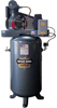
Back by popular demand! We received lots of feedback / visits on the Campbell Hausfeld Air Compressor manual information we posted about a month ago on this blog, so we've decided to continue down the same path! Below, we've posted the same information on Saylor-Beall Air Compressors (Model 703, 705 and 707 pumps) in the hopes that it helps answer some of your questions. Do you have operational questions?
Maybe you are looking for assistance in troubleshooting your compressor or you need part# information? Below we've included assembly, operating, installation instructions as well as a part list. And, as always please do leave comments for us at the end of this post- we always like feedback!
Installation and Operating Instructions (read all instructions before starting compressor)
UNPACKING INSTRUCTIONS The two stage compressor was inspected at the factory and packaged to protect against shipping damage. when you unpack your unit, inspect for damage or missing parts. If there is any damage or missing parts, the transportation company's agent should make a notation to the effect on the Bill of Lading. Claims should be settled directly with the transportation company.
PIPING
If a pipe line is necessary, use the same size as the tank valve since too small piping restricts the flow of air. If over 100 feet long, use the next larger size. Bury underground lines below the frost line and avoid pockets where condensation can gather and freeze. Make certain all pipe joints are free from leaks. Apply pressure before underground lines are covered.
WIRING
Have a certified electrician connect the service wires to the magnetic starter. Check following: 1. The electric box is large enough. Service adequate ampere rating. 2. The supply line has the same electrical characteristics (voltage, cycles, and phase) as the motor. 3. The line wire is the proper size and that no other equipment is operated from the same line. The following chart gives minimum recommended wire sizes for compressor installations. For longer lines, use the next larger size wiring. Various national and local codes and standards have been set up covering electrical apparatus and wiring. These should be consulted and local ordinances observed. Our recommended wire sizes may be larger than the minimum set up by local ordinances. If so, the larger size wire should be used to prevent excessive line voltage drop.
The additional wire cost is very small compared with the cost of repairing or replacing a motor electrically "starved" by the use of too small supply wires.
BELT GUARD
OSHA requires installation of a totally enclosed belt guard covering the flywheel, belts, and motor pulley.
WARNINGS
1. Compressed air systems are complex and can be dangerous. Use an experienced compressed air systems person when connecting this air compressor to any system.
2. Electric motor driven compressors use electricity. Use only a certified electrician to connect to the power source. To avoid risk of electrocution, do not touch or come in contact with any part of the compressor or power lines while it is connected to a power source. Prior to performance of any service or maintenance, disconnect and lock out any source of electricity.
3. Electricity can cause a fire or explosion when directly exposed to flammable chemicals, liquids or gasses. Do not locate the compressor near any dangerous material.
4. Air pressure can cause explosion. Do not fill compressed air into any container beyond its rated air capacity. Do not exceed the pressure rating of any container. Containers may include cylinders, tires, air tools, air tanks, piping, and other items that use compressed air in their normal operation. These items may have a pressure capacity that is lower than the pressure output of this air compressor. Check the manufacturer of any container for its pressure rating prior to inflation.
5. Compressed air can cause injury to the eyes, ears, or body parts. Compressed air is a powerful source of energy that escapes rapidly from devices such as nozzles, hoses, and equipment that are connected to compressed air. Do not allow any part of your body to come in contact directly near compressed air or where compressed air is escaping the system, tools, or equipment.
6. Compressed air may contain carbon monoxide and other impurities. Do not use compressed air as a source of breathing air, or it may cause illness or death.
7. Compressed air can disturb the normal source of breathing air by mixing dust, paint, sand blasting debris, or other impurities into the nearby atmosphere. Always use a breathing filter of adequate capacity when your breathing air has been altered.
8. The air compressor has moving parts that are protected by an enclosed belt guard at the time of manufacture. Do not remove the belt guard, except when performing maintenance. Electric power should be disconnected and locked out as noted in item 2 prior to removal of the guard. To avoid injury, do not touch or come in contact with the air compressor while the power is connected. Keep all loose clothing and other articles away from the compressor while power is connected. The unit may start unexpectedly at any time power is connected.
9. Compressed air, the air compressor, and the compressed air system will be hot while operating. Do not touch any components while in operation to avoid risk of burns.
10. Do not modify or repair an air tank. Welding, drilling or other modifications may weaken the tank resulting in risk of an explosion. Always replace cracked or leaking air tanks.
11. Never install a shutoff valve between the compressor pump and air tank. this is extremely important for base mounted configurations, but also may apply if a tank mounted configuration is modified. Personal injury or equipment damage may occur.
12. This air compressor is designed to compress air only. Do not compress any gas other than air, as an unknown result could occur, included but not limited to damage to the equipment or explosion.
MODEL 703-705-707 PUMPS INSTALLATION AND STARTING
INSPECTION
Check for possible damage in transit. All basic pumps are shipped with flywheel unmounted! Do not force flywheel on crankshaft. Use wedge in "slot" provided for easy assembly. Belt alignment and tensions must be checked carefully!
MOUNTING Install a clean, dry, well ventilated location away from any source of heat such as a boiler or radiator. If a unit is to be fastened to a foundation, all four feet must be firmly supported and shimmed to remove all stress from unit. Pump flywheel should be mounted towards wall with minimum clearance of 18" to allow for circulation of air and additional clearance if required for servicing.
LUBRICATION Fill crankcase to level mark on oil gauge with an industrial compressor oil grade ISO 150 or ASTM 700.
CAUTION: Turn power off before servicing.
MAINTENANCE OPERATION AND CARE PRESSURE AND SPEED
Never operate pump at pressures or speeds in excess of those recommended by factory. Every compressor assembly must have a safety valve installed and should be set at either the maximum tank working pressure or 25 PSI over the actual pressure of the pump, whichever is less.
OPERATING GUIDELINES Maximum operating speed, 703 @ 2 HP, 510 RPM; 705 @ 5 HP, 845 RPM; 707 @ 10 HP, 845 RPM. Minimum operating speed, all pumps, 400 RPM. Intermittent Operation, maximum 70%. Consult dealer for applications outside these guidelines.
DAILY Check for unusual noises, failure to compress, overheating, oil leaks, and vibration. Correct before serious damage develops. Drain all condensate from receiver and traps.
WEEKLY Examine intake filter elements, and if dirty, remove and clean, or replace. Check oil level and add if necessary. Do not fill over level mark on sight glass! Keep compressor clean for efficient operation and appearance.
MONTHLY Check and tighten all bolts and nuts as required (refer to torque chart). Check air connections for air leaks - tighten as required. Check belt tension. NOTE: This is a standard maintenance procedure which "warranty" does not cover. QUARTERLY Inspect valves, clean if necessary. NOTE: This is a standard maintenance procedure which "warranty" does not cover.
MAINTENANCE - TROUBLESHOOTING - REPAIRS SLOW PUMPING OR INSUFFICIENT PRESSURE
1. Clogged filter element - clean or replace
2. Leaks in air lines - re-tighten or replace
3. Insufficient air capacity - add compressor capacity - consult dealer
4. Head valves - clean or replace (see figure 5)
5. Slipping belts - adjust or replace. 6. Incorrect installation - allow 18" minimum between wall and flywheel. 7. Insufficient air capacity or excessive duty cycle.
OVERHEATING 1. Pump running backwards -reverse rotation, must be CCW facing flywheel 2. Inadequate ventilation - pipe intakes to outside and install filters to protect against weather and foreign objects. 3. High ambient - same as #2. 4. Restricted air intakes - clean or replace.
EXCESSIVE OIL CONSUMPTION 1. Too much oil - drain out excess to level mark on sight glass. 2. Worn rings - replace rings. 3. Clogged air intake filters - clean or replace. 4. Improper oil - consult oil chart. 5. Oil leaks - check and tighten all bolts and nuts. Replace gaskets if necessary. See "monthly" under "Operation and Care." 6. Duty cycle over 70%
MODEL 703 PART NUMBERS Crankcase Assembly.... 4539 -Crankcase....4048-R -Oil Sight Glass....6427 Cylinder...4033 Cylinder Head...4121 Intercooler Asssemly....4536 -Intercooler....4063 -Reducer Bushing....4128 -Pipe Plug...4127 -Safety Valve....3587-K Side Cover...4053 Flywheel Assembly...4537 -Flywheel...6445 -Bolt....4135 -Lockwasher....4136 -Nut...4137 Gasket - Cylinder Head....4066 Gasket - Cylinder to Crankcase....4105 Gasket - Front Cover....4111 Gasket - Side Cover....4104 Gasket - Intercooler....4085 Shims - Brg. Adj...6112 Gasket Set-....4310
MODEL 705 PART NUMBERS Crankcase Assembly.... 4539 -Crankcase....4048-R -Oil Sight Glass....6427 Cylinder...4045 Cylinder Head...4122 Intercooler Asssemly....4536 -Intercooler....4063 -Reducer Bushing....4128 -Pipe Plug...4127 -Safety Valve....3587-K Side Cover...4053 Flywheel Assembly...4546 -Flywheel...6445 -Bolt....4135 -Lockwasher....4136 -Nut...4137 Gasket - Cylinder Head....4090 Gasket - Cylinder to Crankcase....4105 Gasket - Front Cover....4111 Gasket - Side Cover....4104 Gasket - Intercooler....4085 Shims - Brg. Adj...6112 Gasket Set-....4311
MODEL 707 PART NUMBERS Crankcase Assembly.... 4547 -Crankcase....3810 -Oil Sight Glass....6427 Cylinder...4045 Cylinder Head RH... 4044 Cylinder Head LH... 4122 Intercooler Asssemly....4536 -Intercooler....4063 -Reducer Bushing....4128 -Pipe Plug...4127 -Safety Valve....3587-K Side Cover...4043 Flywheel Assembly...4807 -Flywheel...6445 -Bolt....4135 -Lockwasher....4136 -Nut...4137 Exhaust Manifold...4190 Elbow - Exhaust Manifold...4191 Gasket - Cylinder Head....4090 Gasket - Cylinder to Crankcase....4105 Gasket - Front Cover....4111 Gasket - Side Cover....4124 Gasket - Intercooler....4085 Shims - Brg. Adj...6112 Gasket - Exhaust Manifold...4203 Gasket Set-....4312 Flat Washer...4316
MODELS 703-705-707 Air Filter Silencer ....6105 Filter Elements (6105)....6106 Oil Bath Intake Filter....4462 Crankcase Breather....S-527 Centrifugal Unloaders ass'y....6108 Safety Valve....4144 Pipe-Oil Drain....4206 Elbow-Oil Drain....4207 Plug-Oil Drain....4208 Head Bolts....4188 Head Bolt....4095 Cylinder Bolts....4380 Side Cover Bolts....966-K Intercooler Bolts....4134 Manifold Bolts....4224 Manifold Bolts....4255 Key-Flywheel....4012 Washer-Cylinder....6077 Washer-Copper....4081 Pipe Plug-Oil Fill....4127
DISASSEMBLY 1. Loosen motor - slide toward pump. Remove belts and flywheel. use wedge in slot of flywheel after loosening bolt. Disconnect aftercooler tube and tube to centrifugal unloader. Remove 4 belts securing pump to base. 2. Remove exhaust manifold (707), cylinder heads, and intercooler. 3. Mark top of pistons for reassembling in same position. 4. Remove side plates 5. To remove connecting rod - remove rod bolts, noting position of the identification marks on one side of each so that connecting rods are re-installed in original position. DO NOT INTERCHANGE ROD CAPS! 6. Remove connecting rod and piston assembly through bottom of cylinder. cylinder must be removed from crankcase. 7. To remove pistons from connecting rod - remove two retaining rings, one on each end of wrist pin - L.P. piston only. "Tap" wrist pin out of piston. 8. To remove crankshaft - remove key from flywheel and burrs or foreign matter to prevent damage to shaft seal. Remove bolts from front cover and remove cover being careful not to let crankshaft drop, *Remove centrifugal unloader, attached to rear end of crankshaft. Slide crankshaft out through front cover. 9. To remove valves from cylinder head - remove (3) valve cover plates (HP intake and exhaust valves). remove threaded plugs (slots are provided for removal) and spacers atop each valve. Lift valves out through openings.
DO NOT INTERCHANGE VALVES! * Centrifugal unloader is assembled and disassembled by screwing the entire assembly into the end of the crankshaft. This assembly is provided with a LEFT HAND THREAD and must be firmly tightened. CAUTION: Incorrect rotation of compressor unit will unscrew this assembly! Rotation must be CCW facing flywheel end. Crankshaft Rod Journal Diameter...1.5630/1.5620 Wrist Pin Diameter....7501/.7497
CAUTION: Wrist pins are a "tap fit" into pistons! DO NOT USE FORCE! Forcing will remove "cam" from LP Pistons, resulting in "galling" of piston. Oversize Bearing Inserts, Piston, and Piston Rings NOT AVAILABLE. REASSEMBLY 1. Crankshaft - install crankshaft into crankcase through front cover hole. Install front cover over crankshaft being careful not to tear shaft seal. Install bolts and tighten. Crankshaft end play is determined by inserting or removing "shims" under rear adapter plate. Shims are provided in three thicknesses and the proper combinations must be selected so the crankshaft may be turned freely in bearings without end play! 2. Cylinder - scored cylinders should be replaced. Break glaze in cylinders if used cylinders are reinstalled. Piston, rings and connecting rod assembly must be assembled in cylinder bores before assembling cylinders. Align rods with crankshaft throws, remove rod caps (DO NOT INTERCHANGE ROD CAPS!), set cylinder on crankcase and install bolts and copper washers - tighten per torque chart. 3. Pistons - clean ring grooves and oil return holes. Assemble connecting rod in piston and push wrist pin through - use "tap fit" on wrist pin - using "force" will remove "cam" from low pressure piston resulting in galling. If wrist pin is slightly tight - heat piston slightly before "tapping" wrist pin in. Install retaining rings on LP piston pins. Rings- install oil ring in bottom groove, followed by stepped scraper ring, and then two compression rings. Stagger ring gaps a minimum of 90 degrees from each other. 4. Connecting Rod - Install the bearing inserts into the rod and cap, fitting the locating projections into grooves provided. Assemble rod cap (after oiling both halves of insert bearing) and tighten. Tap rod cap and rod to "seat" bearing inserts. never file rod cap or use shims to adjust bearing clearance. Install connecting rod into piston per step 3 and piston and rod assembly into cylinder per step 2. when inserting piston and rod assembly into cylinder bore compress rings to prevent breaking and scoring of cylinder wall. 5. Cylinder Head- install valves and components (as shown in Figure 5) being careful not to interchange valves - tighten per torque chart. Install cylinder head assembly on cylinder, install bolts and tighten. Install intercooler and exhaust manifold (707). 6. Turn pump over by "hand" before starting. It is recommended that the pump be "run in" a few hours. WARRANTY As an authorized Saylor-Beall air compressor dealer, Clark Heintz Tools & Equipment LLC warrants all of its compressors.