
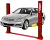
Below you will find the Handy Motorcycle Lift SAM 1000 Instructions and Parts diagrams and lists. We find its been helpful for folks perusing our blog to post documents provided by some of our manufacturer partners. We post all of these PDFs on our website as they become available to us (you will find this particular pdf in the product description for the Handy SAM 1000), but since they are setup as a clickable link, sometimes they can get overlooked. We are grateful for your feedback as it steers us in the right direction - please keep it coming! We are always interested in learning more about what you'd like to see on this blog! Best wishes for a Happy New Year, Clark Heintz Tools & Equipment LLC HANDY S.A.M 1000 AIR LIFT
PARTS LIST AND INSTRUCTION  1. Center load on table - 1000 lb. maximum.
2. Connect to 100 psi maximum shop air.
3. Keep safety bar in position at all times - except when lowering.
4. Keep hands and tools from under carriage. 5. Do not mount table when in elevated position.
6. Do not ride vehicle onto lift.
7. Lift must be in the lowered position when moving.
8. Only trained persons should operate Air Lift.
9. The working area should be sufficiently lit.
10. Foot controller should be at least 3 feet away from Air Lift during raising and lowering operation.
11. Lift is recommended for indoor use only.
INSTRUCTIONS UNPACKING AND SET-UP
1. Open carton, then remove ramp and shipping boards.
2. CAREFULLY TURN TABLE UPRIGHT INTO OPERATING POSITION BEFORE REMOVING SHIPPING CABLE RESTRAINT FROM SCISSOR MECHANISM.
3. Connect foot-operated air valve to 100 psi maximum air supply. The lift may be damaged and/or personal injury may result if the pressure exceeds the maximum 100 psi rating.
4. Stand clear of lift table, and depress the UP side of foot valve to raise table.
5. To lower table, lift detent bar from safety latch and lower to next position or to floor.
6. Place drop-out cover over dropout opening.
7. Insert ramp mounting pins into holes at either end of table to mount ramp.
NOTE: If cycle vise is being installed, ramp must be mounted opposite the cycle vise. OPERATION
1. Loads must be centered on table at all times. Table is rated for a maximum load of 1000 lbs.
2. Loads must be firmly positioned and secured on table at all times.
3. All moving parts have been lubricated at the factory and should be re-lubricated every (6) months to prevent galling. Grease zerks are located at each end of frame pivot shaft and at top ends of inside frame assembly.
4. Lightly oil cylinder rod when it becomes dry.
5. Squirt some oil through bleed hole in plate end of cylinder to lubricate piston and its seal every (6) months.
6. Pivot shaft set screws should be checked frequently to be sure they are tight. These are located at the top end of the inside frame assembly. OTHER OPTIONS AVAILABLE Separate installation instructions included with each option. PART # DESCRIPTION 14476 CV-17 CYCLE VISE – Used to stabilize motorcycles while on lift 16002 12” SIDE EXTENSIONS (2) - Expands width of lift from 24” to 48” includes stabilizer bar. 16001 13” FRONT EXTENSION – Extends lift top to 97” for longer wheel base motorcycles 10732 LIFT DOLLY – Helps move lift while in down position 
PART # DESCRIPTION 10819 dentent clip 14381 valve hose with fitting 11250 screw 3/4 - 10 x 1 3/4 11253 retaining ring 1 5/16 11255 lockwasher 3/4" 11319 wheel 12887 valve stern assembly 12937 foot valve assembly complete 13304 cylinder shaft bushing 13305 cylinder shaft seal 11061 cylinder 11071 cylinder shaft assembly 11315 cam roller bearing 11252 retaining ring 11308 piston 11306 piston seal 11065 cylinder end plate 11250 screw 3/4 - 10 x 1 3/4 11316 cam bearing space 15685 top assembly 11225 inside frame assembly 11222 outside frame assembly 11123 ramp 15687 dropout cover 11177 detent bar 11179 frame pivot shaft 11008 cylinder pivot shaft 11254 retaining ring 1 1/4 11321 track roller bearing 11253 retaining ring 11248 1/2 x 1 3/4 clevis pin 11249 cotter pin 1/8 x 7/8


